DIY: 92-00 Civic Wheel Bearing Replacement
 10-Sep-2010, 12:31 AM
#1
Senior Member
Thread Starter
Join Date: Oct 2007
Location: Toronto
Posts: 131
DIY: 92-00 Civic Wheel Bearing Replacement
I know this is probably straight forward for most mechanically-inclined people, but it may be beneficial to other noobs like me.
Tools you'll need:
- hammer(s)
- 10mm, 17mm and 32mm sockets and wrench
- torque wrench
- impact wrench (optional)
- philps screw driver
- jack
- jack stands
- new wheel bearing
- hydraulic press
- plypar (optional)
- patience!!!
- 3 cotter pins (for each front wheel)


To replace your wheel bearing, basically we gotta remove the knuckle from your car. The following diagram illustrates the three nuts (A, B and C) that need to be removed to set knuckle free

Directions:
1) If possible, remove the centre caps from your wheels in order for the 32mm axel nut to become visible and crack that baby loose. If you don't have centre caps or if this isn't possible for some other reason, don't worry, you can do this later when the car is raised and wheels are removed. Note: It's a bitch to remove this axel nut because it's in there really tight, so you'll have to put some muscle into it. Use either a long wrench or an impact wrench. I used both!


2) Raise the car and put it on jack stands. If you couldn't remove the axel nut for the above reasons, do it now.

3) We will proceed by taking off the brake caliper. There are two 17mm screws that mount the caliper to the knuckle. Remove them


4) After the caliper is off, remove the brake rotor. There are two philp screws that hold it in... you may need to use an impact wrench if you've never removed them before.


This is what everything should look like now... caliper, rotor and axle nut removed

5) Now we need to take off the three castle nuts presented in this diagram. They all have cotter pins which also need to be removed.


Note: In the following image, you can see the rotor, but this should already be off.

6) If your car has ABS, you will need to remove the sensor from the knuckle. There are four 10mm bolts.


7) Now CAREFULLY take out the knuckle. You may need to use a prybar for the castle nut under the lower ball joint. The axle should slide right out. If it doesn't, tap it LIGHTLY with a hammer.


You can see the wheel bearing by turning the knuckle backwards

8) In order to take out the wheel bearing, you will need to first press out the hub and then after removing the c-clamp, you can also press out the wheel bearing. I had a friend do this for me since I don't have a hydralic press. I've seen some people use a hammer and a few large washers to do this. Part Source or some other automotive shops also have a tool you can usually rent to do this.


The following is taken from a thread on HT explaining how to remove the hub and wheel bearing manually and pressing in the new bearing (Write-Up: DIY Front Wheel Bearing Replacement - Honda-Tech
Here is my new bearing purchased from Honda and installed. On that note, I would recommend buying OEM parts because I am doing this to replace an aftermarket wheel bearing I got about 1.5 yrs ago.


9) Install the knuckle and ABS sensor following the steps you used to take it out (in reverse order).

10) Don't forget to make sure everything is tightened to spec. Also make sure you use NEW cotter pins for the three castle nuts you removed.
A - 29-35 ft-lbs
B - 33 ft-lbs
C - 36-43 ft-lbs
11) Install your rotors and brake calipers. My mounting bolts for the calipers had to be tightened to 40 ft-lbs, but I think the stock ones should be around 80.

12) Tighen the axel nut, making sure the pivot sits in the correct spot (You will need to push it in using a hammer and something that's not too sharp). Note: I tightened the axle nut after taking the car off jack stands since it needs to be on really tight. You can also have a friend apply the brakes while you tighten it (when the car is still raised).
13) Put the wheels back on, lower the car from the jack stands and you're all done! Now go for a test drive!
Tools you'll need:
- hammer(s)
- 10mm, 17mm and 32mm sockets and wrench
- torque wrench
- impact wrench (optional)
- philps screw driver
- jack
- jack stands
- new wheel bearing
- hydraulic press
- plypar (optional)
- patience!!!
- 3 cotter pins (for each front wheel)
To replace your wheel bearing, basically we gotta remove the knuckle from your car. The following diagram illustrates the three nuts (A, B and C) that need to be removed to set knuckle free
Directions:
1) If possible, remove the centre caps from your wheels in order for the 32mm axel nut to become visible and crack that baby loose. If you don't have centre caps or if this isn't possible for some other reason, don't worry, you can do this later when the car is raised and wheels are removed. Note: It's a bitch to remove this axel nut because it's in there really tight, so you'll have to put some muscle into it. Use either a long wrench or an impact wrench. I used both!
2) Raise the car and put it on jack stands. If you couldn't remove the axel nut for the above reasons, do it now.
3) We will proceed by taking off the brake caliper. There are two 17mm screws that mount the caliper to the knuckle. Remove them
4) After the caliper is off, remove the brake rotor. There are two philp screws that hold it in... you may need to use an impact wrench if you've never removed them before.
This is what everything should look like now... caliper, rotor and axle nut removed
5) Now we need to take off the three castle nuts presented in this diagram. They all have cotter pins which also need to be removed.
Note: In the following image, you can see the rotor, but this should already be off.
6) If your car has ABS, you will need to remove the sensor from the knuckle. There are four 10mm bolts.
7) Now CAREFULLY take out the knuckle. You may need to use a prybar for the castle nut under the lower ball joint. The axle should slide right out. If it doesn't, tap it LIGHTLY with a hammer.
You can see the wheel bearing by turning the knuckle backwards
8) In order to take out the wheel bearing, you will need to first press out the hub and then after removing the c-clamp, you can also press out the wheel bearing. I had a friend do this for me since I don't have a hydralic press. I've seen some people use a hammer and a few large washers to do this. Part Source or some other automotive shops also have a tool you can usually rent to do this.
The following is taken from a thread on HT explaining how to remove the hub and wheel bearing manually and pressing in the new bearing (Write-Up: DIY Front Wheel Bearing Replacement - Honda-Tech
Step A) Set up your socket how it is in the picture below and get your 3 LB hammer ready (or whatever you are going to use that is about 1-3/8� Outer Diameter). Pound out the Hub (don�t worry part of the wheel bearing inner race will come with it).

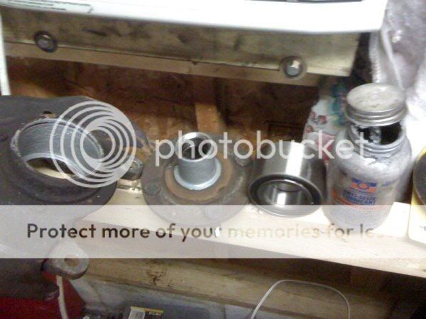
Step B) After you have hammered out the Hub you should have half of the inner wheel bearing race stuck on it if you are unlucky. The next object is to get the Hub on the left to look like the one on the right in the picture below.

Step C) Now to remove the inner race from the Hub with out special tools is a delicate task. You could use a bearing puller and a gear puller or a press but those are all special tools most don�t have. Take your grinder and buzz off the material as seen in the picture. When you get close to the Hub shaft it will start to discolor, turning black/ blue/ purple. The part of the wheel bearing race that is more towards the wheel studs is thicker. Be sure you understand where the separation is; THERE IS A GAP BETWEEN THE HUB FACE AND THE BEARING RACE! If you nick a little bit of the Hub shaft don�t worry. Just don�t gouge it severely. You can get it close then use the chisel to break it through the rest of the way. After you get a gap take your Channel Locks and �walk it off� by turning it back and forth. Be sure to take a file or some emery cloth if you nick up the surface. You don�t want the bearing �hanging up or sticking� on an imperfection.

Step D) There is an internal snap ring on the front side of the wheel bearing you have to remove. This can be done with a pair of needle nose pliers (if you have a snap ring tool then great, use that instead). I like to take a hammer and screwdriver to sort of �pop� the ring out of its rusted seat; then use the pliers to easily pull it out. (Sorry, I forgot to snap a picture BEFORE I took it out so I had to take one after I put the new one in.)

Step E) Now is time to pound out the wheel bearing. I like to spray it down with some PB Blaster or WD-40 on both sides before I start. You don�t have to, but can if you have the stuff. I like using the 6 LB hammer sitting on the wheel bearing and hitting it with the 3 LB. You can use a socket if you like but it has to be about 2-1/4� OD to work right.


Step F) Now wipe out the spindle and the shaft of the Hub. You don�t have to use Anti-Seize if you don�t want to but you will want to use some type of lubricant like oil. I am in love with anti-seize and use it on everything possible. I hate trying to fight stuff if I ever have to pull it back apart. Anti-seize the Hub shaft and the inside of the spindle where the bearing sits.
Step G) Now for the good stuff. If you take your new wheel bearing (if you haven�t figured it out yet) the outside race is one piece and the inside race is two pieces. This poses a problem when you are putting in the Hub, but we will get to that later as it is easily overcame.
If you put the wheel bearing into the hole you will notice it goes in a little bit, around 1/4� to 3/8�. This will help you get it aligned correctly. Now when I talked about earlier it all depends on what type of setup you use� this is where that all kicks in. I used 7/8� Threaded Stock. The 7/8� washer fits perfectly in the front side for pressing the Hub in. See back to the top if you are confused on what you should use. (Arranging your washers/ plates accordingly to get the desired effect.) You need the 3� diameter piece to go on the backside of the spindle and rest on the edge. On the front side you will need the 2-3/4� diameter to go on the bearing and be sure to center the washer so it does not hang up on the spindle edge while the bearing is being pressed in.

Step H) Now get your �� impact ready (you don�t technically need one but you will be one tired Mother EF�er when you are done if you don�t have one). Use your combination or adjustable on the other side as shown in the picture and press her in until the socket stops turning.

Step I) Take out your bolt setup and get ready for the next piece, the Hub. Doing the same with arranging the washers/plates to get the desired effect; you will need 2� to go on the backside of the bearing (keeping the inner race from falling out) and a 1-3/4� to go in the �cup� of the front of the Hub. Some say you can use the axle to do this but I looked at it and there is practically NO WAY to do it with the axle� Now take the Hub and line it up, put your assembly together and push her in like the wheel bearing. You will go until it stops.

Pat yourself on the back because you just did your own wheel bearing!!!

Step B) After you have hammered out the Hub you should have half of the inner wheel bearing race stuck on it if you are unlucky. The next object is to get the Hub on the left to look like the one on the right in the picture below.
Step C) Now to remove the inner race from the Hub with out special tools is a delicate task. You could use a bearing puller and a gear puller or a press but those are all special tools most don�t have. Take your grinder and buzz off the material as seen in the picture. When you get close to the Hub shaft it will start to discolor, turning black/ blue/ purple. The part of the wheel bearing race that is more towards the wheel studs is thicker. Be sure you understand where the separation is; THERE IS A GAP BETWEEN THE HUB FACE AND THE BEARING RACE! If you nick a little bit of the Hub shaft don�t worry. Just don�t gouge it severely. You can get it close then use the chisel to break it through the rest of the way. After you get a gap take your Channel Locks and �walk it off� by turning it back and forth. Be sure to take a file or some emery cloth if you nick up the surface. You don�t want the bearing �hanging up or sticking� on an imperfection.
Step D) There is an internal snap ring on the front side of the wheel bearing you have to remove. This can be done with a pair of needle nose pliers (if you have a snap ring tool then great, use that instead). I like to take a hammer and screwdriver to sort of �pop� the ring out of its rusted seat; then use the pliers to easily pull it out. (Sorry, I forgot to snap a picture BEFORE I took it out so I had to take one after I put the new one in.)
Step E) Now is time to pound out the wheel bearing. I like to spray it down with some PB Blaster or WD-40 on both sides before I start. You don�t have to, but can if you have the stuff. I like using the 6 LB hammer sitting on the wheel bearing and hitting it with the 3 LB. You can use a socket if you like but it has to be about 2-1/4� OD to work right.
Step F) Now wipe out the spindle and the shaft of the Hub. You don�t have to use Anti-Seize if you don�t want to but you will want to use some type of lubricant like oil. I am in love with anti-seize and use it on everything possible. I hate trying to fight stuff if I ever have to pull it back apart. Anti-seize the Hub shaft and the inside of the spindle where the bearing sits.
Step G) Now for the good stuff. If you take your new wheel bearing (if you haven�t figured it out yet) the outside race is one piece and the inside race is two pieces. This poses a problem when you are putting in the Hub, but we will get to that later as it is easily overcame.
If you put the wheel bearing into the hole you will notice it goes in a little bit, around 1/4� to 3/8�. This will help you get it aligned correctly. Now when I talked about earlier it all depends on what type of setup you use� this is where that all kicks in. I used 7/8� Threaded Stock. The 7/8� washer fits perfectly in the front side for pressing the Hub in. See back to the top if you are confused on what you should use. (Arranging your washers/ plates accordingly to get the desired effect.) You need the 3� diameter piece to go on the backside of the spindle and rest on the edge. On the front side you will need the 2-3/4� diameter to go on the bearing and be sure to center the washer so it does not hang up on the spindle edge while the bearing is being pressed in.
Step H) Now get your �� impact ready (you don�t technically need one but you will be one tired Mother EF�er when you are done if you don�t have one). Use your combination or adjustable on the other side as shown in the picture and press her in until the socket stops turning.
Step I) Take out your bolt setup and get ready for the next piece, the Hub. Doing the same with arranging the washers/plates to get the desired effect; you will need 2� to go on the backside of the bearing (keeping the inner race from falling out) and a 1-3/4� to go in the �cup� of the front of the Hub. Some say you can use the axle to do this but I looked at it and there is practically NO WAY to do it with the axle� Now take the Hub and line it up, put your assembly together and push her in like the wheel bearing. You will go until it stops.
Pat yourself on the back because you just did your own wheel bearing!!!
Here is my new bearing purchased from Honda and installed. On that note, I would recommend buying OEM parts because I am doing this to replace an aftermarket wheel bearing I got about 1.5 yrs ago.
9) Install the knuckle and ABS sensor following the steps you used to take it out (in reverse order).
10) Don't forget to make sure everything is tightened to spec. Also make sure you use NEW cotter pins for the three castle nuts you removed.
A - 29-35 ft-lbs
B - 33 ft-lbs
C - 36-43 ft-lbs
11) Install your rotors and brake calipers. My mounting bolts for the calipers had to be tightened to 40 ft-lbs, but I think the stock ones should be around 80.
12) Tighen the axel nut, making sure the pivot sits in the correct spot (You will need to push it in using a hammer and something that's not too sharp). Note: I tightened the axle nut after taking the car off jack stands since it needs to be on really tight. You can also have a friend apply the brakes while you tighten it (when the car is still raised).
13) Put the wheels back on, lower the car from the jack stands and you're all done! Now go for a test drive!


 02-Oct-2010, 12:57 AM
#7
Senior Member

Join Date: Feb 2010
Location: Waterloo, Ontario
Posts: 1,074
lol crappy tools ftl. snap-on or nothing.. you CAN feel a difference. anyways some corrections/additions
first off, make sure you actually need to replace the wheel bearing. do this by grabbing your wheel at 12 oclock and 6 oclock while the car is jacked up. with both hands on the wheel at top and bottom, wiggle in and out, if there is movement or it feels loose then your wheel bearing has "play". other ways of telling are to listen for the bearing being noisy (spin wheel while jacked up), having a licensed technician examine it.
Tools you'll need:
- hammer(s)
- 10mm, 17mm and 32mm sockets and wrench
- torque wrench
- impact wrench (optional)
- philps screw driver
- jack
- jack stands
- new wheel bearing
- hydraulic press
- plypar (optional)
- patience!!!
- 3 cotter pins (for each front wheel)
-anti-seize
-lock-tite
-impact driver (optional)
To replace your wheel bearing, basically we gotta remove the knuckle from your car. The following diagram illustrates the three nuts (A, B and C) that need to be removed to set knuckle free for those who want to know what your taking off..: lower balljoint, upper balljoint, outer tie-rod
1) If possible, remove the centre caps from your wheels in order for the 32mm axel nut to become visible and crack that baby loose. If you don't have centre caps or if this isn't possible for some other reason, don't worry, you can do this later when the car is raised and wheels are removed. Note: It's a bitch to remove this axel nut because it's in there really tight, so you'll have to put some muscle into it. Use either a long wrench or an impact wrench. I used both! a breaker-bar would be easiest/fastest if air tools aren't abailable
2) Raise the car and put it on jack stands. If you couldn't remove the axel nut for the above reasons, do it now. block the wheels
3) We will proceed by taking off the brake caliper. There are two 17mm screws that mount the caliper to the knuckle. Remove them
4) After the caliper is off, remove the brake rotor. There are two philip screws that hold it in... you may need to use an impact wrench if you've never removed them before. use an impact driver with proper philips head attachment on it
This is what everything should look like now... caliper, rotor and axle nut removed
5) Now we need to take off the three castle nuts presented in this diagram. They all have cotter pins which also need to be removed.
6) If your car has ABS, you will need to remove the sensor from the knuckle. There are four 10mm bolts.
7) Now CAREFULLY take out the knuckle. You may need to use a prybar for the castle nut under the lower ball joint. The axle should slide right out. If it doesn't, tap it LIGHTLY with a hammer.[/I] do not hit the threaded part of the balljoint with a hammer. you can smack the knuckle itself where it meets the balljoint, just be carefull not to damage the bj
You can see the wheel bearing by turning the knuckle backwards
8) In order to take out the wheel bearing, you will need to first press out the hub and then after removing the c-clamp, you can also press out the wheel bearing. I had a friend do this for me since I don't have a hydralic press. I've seen some people use a hammer and a few large washers to do this. Part Source or some other automotive shops also have a tool you can usually rent to do this. do NOT use a hammer and washers... ever
The following is taken from a thread on HT explaining how to remove the hub and wheel bearing manually and pressing in the new bearing
Here is my new bearing purchased from Honda and installed. On that note, I would recommend buying OEM parts because I am doing this to replace an aftermarket wheel bearing I got about 1.5 yrs ago.
9) Install the knuckle and ABS sensor following the steps you used to take it out (in reverse order).
10) Don't forget to make sure everything is tightened to spec. Also make sure you use NEW cotter pins for the three castle nuts you removed.
use a torque wrench and always tighten to oem specifications
A - 29-35 ft-lbs
B - 33 ft-lbs
C - 36-43 ft-lbs
11) Install your rotors and brake calipers. My mounting bolts for the calipers had to be tightened to 40 ft-lbs, but I think the stock ones should be around 80. use anti-seize on the caliper bracket bolts, and lock-tite on the caliper bolts. both these prevent bolts backing off, and make it simpler to remove the next time
12) Tighen the axel nut, making sure the pivot sits in the correct spot (You will need to push it in using a hammer and something that's not too sharp). Note: I tightened the axle nut after taking the car off jack stands since it needs to be on really tight. You can also have a friend apply the brakes while you tighten it (when the car is still raised).torque the axle nut to the SPECIFIC torque spec. then hammer in a new indent to the nut wherever the slit in the axle is (use a hammer and punch/chisel
13) Put the wheels back on, lower the car from the jack stands and you're all done! Now go for a test drive!torque your lug nuts!!! 100 ft pounds

Thread
Thread Starter
Forum
Replies
Last Post
W O T
Honda Civic Performance - JDM Discussion
17
06-Jan-2007 11:46 AM
imported_teflon
Honda Civic Performance - JDM Discussion
1
04-Jun-2005 10:55 PM
imported_D dot T
Honda Civic Performance - JDM Discussion
20
22-May-2005 02:18 AM
imported_Torrey
Honda Civic Performance - JDM Discussion
18
23-Jan-2005 11:25 PM


